I’m inching closer to first flight. All the paperwork is prepared, Weight & Balance is done, and the formal control system checks have been carried out and signed off by myself and a second authorized person. An avionics LAME is booked for next Monday, Sep 30, to do the necessary pitot-static and transponder tests. In the meantime, today was the day for the first engine run with the cowls on, and taxi testing. After an initial engine run, we started up again and did some careful taxi tests on the apron outside the Hangar.
First taxi tests on the Apron
Once that all looked good, we got a clearance out to the runway at Hobart airport. It was a quiet time and the tower were happy to give us a clearance and get their first look at VH-XVG. Here are two videos, one on the way out to the runway, and then on runway 30 at YMHB, doing the beginning of a mini take-off roll followed by some S-turns.
On the way out to runway 30 YMHBFaking a takeoff roll and doing some S-turns on runway 30, YMHB
Inspections after returning to the Hangar revealed nothing untoward. I downloaded the EFIS logs and the maximum CHT reached during this test was a cool 312 degrees F. The underside of the cowl was at ambient temperature to touch, indicating that the Fiberfrax insulation on the inside of the bottom cowl was doing a great job.
It was a bit surreal to see XVG venture out into the world today after a 10 year all-slow-build RV-10 project. I stayed behind while test pilot Kayle did these runs, because I was getting over a cold and didn’t want to share it. But in a way, it was better because I got to carefully view it all from the outside while still keeping in touch with Kayle on the phone.
After several months spent finishing the engine installation, on May 3, 2024 I finally attempted some engine ground runs.
In preparation for this, I tried to pre-oil the engine by removing plugs and cranking with the starter motor, as is commonly done. After four 15 second cranks, I still didn’t have any indication of oil pressure. I tested the sensor, EFIS display, and the oil sensor restrictor fitting on the engine, they were all OK. It may have come good with continued cranking, but I felt this was simply the oil pump being totally dry (=> unprimed) after years of storage – with air gaps between the teeth and pump walls instead of retained oil held in place by surface tension – so I decided to give it some help. Not having a pressure pre-oiler, I removed the oil filter (which is on a 90 degree B&C adapter), and with a cheap new oil can and extension tubing, squirted engine oil into the filter inlet gallery until it filled up. I then had a helper gently wind the prop backwards, one blade at a time, and kept refilling the space with oil. This sucked oil back into the oil pump, and coated all 360 degrees of the gears. With the oil filter re-installed, I then cranked the engine for 15 seconds, with still no indication of oil pressure. That’s not surprising, the sensor pickup is at the end of a chain which would include filling the oil filter and galleries after the oil filter outlet with oil. Sure enough, about 5 seconds into a second 15 second crank, the oil pressure came up and by the time I was done indicated in excess of 30 psi. After that I reinstalled the plugs and prepared the engine for first start.
To do these engine runs, I had heavy rubber chocks on the main wheels, and tied the tail down (with weights). And of course I had my feet on the brakes. I also had two helpers on the ground, with fire extinguishers handy. In the videos you’ll see me talking, apart from checklist items I had a phone link open to one of the ground helpers in case they told me to stop!
The first run was simply to confirm the engine goes, get oil pumped throughout the engine, and test each ignition system without going above 1200 rpm. It took a fair bit of cranking to get started – I think I did not have it sufficiently primed – and I was about to give the starter motor a rest when it fired. After this the run went fine, for a total of around 3 minutes and the CHT’s never got above 220F. There was a normal RPM drop when I disabled the left ignition system, and one backfire when I disabled the right ignition system, but then a normal RPM drop so something to look into there. Here’s a shortened video of the start and finish of this run:
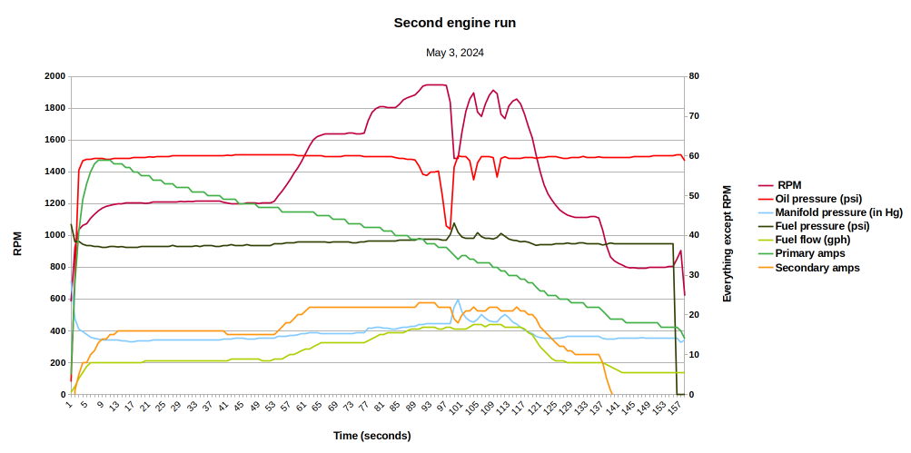
After inspecting for leaks etc. and taking a break, we did a second engine run. This second run was to get the governor and propeller pitch control going. These won’t work until oil has been forced through the governor and into the propeller hub, and that takes more time and some sustained oil pressure at higher rpm. To do this, after a short warmup I took the engine up to around 1900 rpm, pulled the propeller pitch control back to a course setting, and waited. It took around 35 seconds for the propeller pitch to kick in, but I must admit I was expecting it to take longer and was slow pushing the pitch control forward again. As a result the transition to course pitch was a bit more severe than one would normally do for a ground test. I followed this with two more propeller pitch tests, again at 1900 rpm, before pulling the throttle back and ending the run.
A day later I downloaded the EFIS log data, and came up with the following plot for this run. It shows how I did the ramp up to ~1900 RPM cautiously in a few steps. The oil pressure drops before each propeller pitch event (as the governor becomes an oil sink), and along with the RPM drop there is an accompanying increase in manifold pressure. These changes are all as expected. Also on this plot are the primary and secondary alternator currents. The primary alternator current peaks at its rated 60 Amps not long after startup, but the battery was fully charged to begin with so the primary alternator only had to replace capacity lost due to cranking, which it was clearly able to mostly do across the short duration of this engine run. The secondary (vacuum pad) mounted alternator did some work as well, mostly at higher RPM’s, this type of alternator tends to have poor output at low engine RPM.
At the end of the test, fuel pressure drops to zero because I turned the (SDSEFI) fuel pump off. The engine RPM increased momentarily before stopping. This happens because as the fuel pressure drops, the engine sees a leaner mixture. Leaning from a rich mixture, the flame front propagation speeds up – i.e. the mixture burns faster, efficiency improves, and RPM momentarily increases. At some point we cross best stoichiometry (ideal mixture) after which the RPM will drop, the remaining residual fuel runs out and the engine stops.
Very happy to get these tests completed, and to have some good data confirming the test results. A special thanks to my neighbor Dickie and wife Kerrie, for ground assistance and camera work.
There are a few things to tidy up in the engine and cowl installation, then I need to install all the seat belts, a few inside panels, etc. before doing the weight and balance measurements, some more ground and then taxi tests, avionics certification and paperwork leading up to approval to commence phase 1 flight testing.
It took some time to get back to my “Showplanes Cowl with A/C left hand inlet plenum problem”, but this week I finally unleashed my new 3D printer on the problem, and the result was great.
This is a complex part, and I evaluated several different slicing applications to figure out how to do the necessary support structures. I wound up using Cura, because of its “Tree” support capabilities. It generates all sorts of weird tree trunk/branch constructs to support the part while it is being printed. This results in less interference between the support and the part.
It took 4 days 16 hours to print the part in ASA, using a bed temperature of 100 deg C and a 0.4mm nozzle at 250 deg C. I did gear up to use a dissolve-able filament (HIPS) between the support and the part, but decided for the first trial to simply use the one extruder. As it turned out, the support was easy to rip away with a pair of pliers, so I’ll stick with the single material process to save time and complexity.
There were a few areas where the support came slightly adrift, causing rough regions on the part. I need to fix this by manipulating the support to have better adhesion to the bed. It takes about 5 hours to render the model, another hour or so to “repair” the STL, and about an hour to slice the result and generate gcode for the printer. Although the part as printed is certainly usable, there are areas I can improve on. Since each printed part is a 5 day exercise from start to finish, and comes with a filament cost, I won’t be spinning revisions too often.
There are some new materials around, Polyamide with Carbon Fiber filler, which are stronger and have higher operating temperatures, up to 180 degrees C. I can print these materials if I install a hardened nozzle on the printer, but I’ll hold off on this until late in the build because the filament is expensive, and there are new products hitting the market all the time.
For now, I have the entire process under my own control and I’ve been able to print a perfectly acceptable part – mission accomplished for the inlet plenum, finally. Now I can finish the front baffles in this area.
How many hours have I spent on this? A lot, between assembling the printer from parts, calibration, printing test parts, evaluating slicer software and monitoring the printing of the plenum. None of this is really direct work on the air frame, so I’m going to simply log 1 hour for this activity, knowing full well that it was many times this.
Starting the inlet plenum print, layer 1
A day in, and a long way to go
A bit over half way
Nearing the end
Print complete!
Support rips away quite easily
Complete part less support
Installed - and a perfect fit!
2 inch connection is for heat muff SCAT tube
Room for A/C connections
A/C line connections will work OK
Air filter fits inside here, fits into standard Showplanes system
Construction work has been spotty for the past few months due to some work commitments. Time to catch up on a few posts.
I received the prototype 3D printed inlet plenum, after a very long delay caused by Covid-19, a shipment lost in customs, reprinting a replacement, more shipping delays etc. This part was printed in ASA material by a vendor in Sweden. Quality is good apart from some areas where the wall thickness should have been greater.
The part fitted perfectly around / through the compressor, the air filter shroud mount etc. The inlet ramp was also good, perfectly horizontal and lined up with the opposite side (standard Showplanes fiberglass plenum) within 1mm, which is good enough for me. The front edge of the inlet ramp is too far forward, requiring me to trim too much of the cowling. While it would work, it doesn’t leave as much of the cowling inlet hole as I’d like, to get nutplates and some sort of overlapping seal in there. This is one of the areas where the wall thickness is also a bit low. Clearance on the bottom side to the cowling is good, a bit over 1/8″ at the closest point. The rear scat tube connection for a heat muff is also good.
Overall, close to a hole in one which I’m relieved about given how complex the part is. I can now proceed to finish the front of the baffles and around the governor. I’m going to need to address the wall thickness issue and trim back the front edge, which means re-printing the part. These are simple adjustments but I’m going to also look at whether any better alternatives exist than the ASA material I’ve used.
It’s really hard to see much from the pictures, because the 3D printed part is black, but they show the general idea.
Prototype inlet plenum in place
A/C fitting clearance OK
A/C fitting clearance OK
Prototype inlet plenum in place
Good fit around A/C and into air filter shroud
Good fit around A/C and into air filter shroud
Horizontal, and about 1mm below right hand side plenum - good enough
Over the past month I’ve had to deal with something that was always going to stop the project dead in its tracks – sorting out how to mount an Airflow Systems A/C compressor inside a Showplanes cowl. The main problems are:
The A/C compressor doesn’t fit – it smashes into the cowl
The A/C compressor occupies almost all of the space normally used for the left hand air inlet plenum
I’ve seen other build efforts that range from leaving out the left hand induction air plenum entirely, to an A/C compressor mount position that occupies a good part of the area of the left hand inlet duct – in turn compromising the cooling air for cylinders #2, 4 and 6.
Recent efforts in Australia, such as this one, use a longer arm on the A/C mount to drop the compressor down low, and make a bump on the bottom cowling to suit. Armed with the latest mount kit from AFS, I proceeded to test mount the A/C compressor, and immediately ran into quite a bit more trouble than I had expected.
Tensioner wheel, bracket
The supplied drive system simply didn’t work. The tensioner (idler) wheel, using the supplied bracket, hits the starter motor. I can see that with the previous “short” arm, the system would swing up higher and that would free up enough room for the idler wheel to swing past the starter motor. I sent feedback to AFS about this but received no reply. After consulting with the Australian builder referenced above, it turns out the solution was to:
Add spacers, for a total of 7/16″ of spacing, to the engine mount. This moved the entire compressor assembly “away” from the starter motor by 7/16″.
Machine a replacement idler pulley, which was the same size as the AFS supplied pulley, but without the ridges on each edge – saving around 1.5mm of edge distance.
Make a longer arm, even longer than the “long” one AFS supply
I started making up additional spacers (AFS supplies three 0,063″ spacers), using 0.063″ Alclad, but I was only able to add two of these before I ran out of threads on the engine studs used for the A/C mount. I didn’t want to replace these studs, and I didn’t want to switch over to low profile lock nuts – the A/C compressor is quite heavy. So, my spacing limit without resorting to these measures was 0.3″.
The guy who did the VH-BKK installation referenced above graciously had another idler pulley made, and sent it down to me. Armed with this, I still needed to change the position of the idler mount, which means I have to build a new idler mount bracket. I’ve ordered some 6061-T6 plate to do this, in the meantime I drilled a new hole in the existing bracket (rendering it structurally unsound) just to prove I have the hole position correct. This is shown in the following picture, along with the new idler pulley. The clearances everywhere around this are very small, but this is typical and they will be adequate. The idler pulley can now swing up past the starter motor with about 1.5mm of clearance.
I also had to change the Serpentine belt, for this arrangement I fitted a 4PK1130 belt, rather than the 4PK1113 belt provided with the kit – just 17mm longer.
It is necessary to cut out a section on the front of the Showplanes cowl and fiberglass a bump in place to provide adequate clearance for the front of the A/C compressor. There’s nothing hard about this, and one good thing about the Showplanes cowl installation is that the Serpentine belt does not overlap the inlet at all (unlike with the Van’s cowl) – so there is no air leakage associated with treatment to clear the Serpentine belt, and no compromise to cooling air inlet area.
New location of idler hole (dimensions in mm)
Modified tension pulley position
LHS Inlet Plenum
I had expected to solve this problem with various cuts and balloons etc. to the existing inlet plenum. After looking at the problem, I didn’t even attempt it because (a) this was going to beyond my fiberglass skills, and (b) this is probably beyond anyone’s fiberglass skills. There simply isn’t a clear enough path through the maze to make an adequate shape, and unless I could turn the plane upside down, gravity was always going to work against me.
After some soul searching, which included consideration of leaving the A/C system out, I decided to go ahead and create a 3D model of the entire system as a means to 3D print a replacement inlet plenum. The top end is identical to the Showplanes system, using the lower 1/3 of the circular inlet hole for induction air. The plenum has to step down and change shape, wrap around the bottom of the A/C compressor while clearing the bottom cowling, and then join in to a replacement shroud around the existing Showplanes air filter system. Here are some screenshots which include various early prototypes and the final model, which includes an air takeoff to account for the standard Van’s 2″ scat tube outlet for air to a heat muff.
Early model - rear view, showing heat muff scat tube attach point
Early model - Front view, without compressor
Early model - top view showing heat muff air inlet - slot is for Van's supplied mesh screen
Early model - left side view showing heat muff air inlet - slot is for Van's supplied mesh screen
Early model - Induction air inlet, detail showing clearance for Serpentine belt and A/C compressor lug
Early model - Rear view with A/C compressor model in place
Early model - Top view with A/C compressor model in place
Early model - Right side view with A/C compressor model in place
Early model - Front view with A/C compressor model in place
Inadequate clearance for botton A/C fluid connection (early model)
Prototyping with small sections taped together
Prototyping with small sections taped together
Location of A/C cutout in Showplanes cowl
Final model
Final model - Serpentine belt and A/C compressor lug clearance
Final model - Rear air takeoff for heater SCAT hose
Final model - Air filter shroud, note drain hole provision at bottom
Final model - Viewed from bottom front
A/C clearance (note: not fully rendered)
A/C clearance (note: not fully rendered)
Bottom showing fluid connections (note: not fully rendered)
View showing clearance for fluid connections (note: not fully rendered)
Separate shape under design for attachment around Governor
The inlet plenum as shown can be 3D printed in one piece. It is secured at the bottom by three screws in the LH air filter shroud, using nutplates, same as the standard Showplanes arrangement. Around the compressor, two places mount to the A/C compressor lugs using Buna-N rubber spacers, AN3 bolts and washers. The vibration-damping spacers are rated to 200 degrees F which should be adequate. At the top, a flat Alclad plate which extends down from the existing #2 cylinder mounting flange is secured across the heat muff air inlet area, and at the very front of the inlet, using #6 countersink screws with nutplates on the underside of the inlet plenum. One of the front positions uses a low profile nut, embedded in a hex shaped hole, instead of a nutplate.
For the plenum material, the choices are currently between UV resistant ASA, or the more expensive UV resistant tough resin. Both have high glass transition temperatures and adequate chemical resistance. The plenum does not extend back too close to cylinder #2.
To prototype the system, I printed the plenum in sections on my cheap consumer grade 3D printer, using PLA, and taped the parts together. It takes about 100 hours of printing time to do the complete model, and I’ve made several revisions to refine the design and fix up the various maths mistakes I made along the way. It’s been a laborious process but I’m happy enough with the end result. It takes a high end desktop platform 15 hours to render the model in suitably fine detail, and a bit of repair processing to derive the final STL file. I uploaded the (64MB) STL file to http://www.craftcloud3d.com and was quoted just over U$200 to print the model in Black UV resistant ASA, with 40% infill.
Just today I pulled the trigger and ordered the final article, it’s being printed by a vendor in Sweden, and will be delivered here within two weeks. There is still a chance that the final piece will require some small adjustments. There’s a limit to how far I can go with taped together sections, and how many times I can re-measure everything. The final model is way more complex than I had expected, and has consumed far too much time, I’m tired of fretting about it so it’s a relief to get it off my desk.
In the meantime, there are a few other, much simpler pieces I can design to help with the baffling around the governor etc. I’ll complete these, but mostly I’ll be getting back to actual, real, physical work on the project – there is a lot still to do.
I’ve hung the engine, which took all of 20 minutes once I worked out how best to do it. It’ll have to come off again, so I’m leaving the engine lift set up. It has to come off again for several reasons:
The biggest reason – I have to do something with the sump oil line associated with the Barrett cold air induction scheme. There’s a VAF thread about it – here. This whole topic deserves a complete post, which I’ll do once I decide how to deal with it. Suffice to say, it is a nasty issue but until I have a strategy for this I can’t oil the engine.
With a B&C 90 degree oil filter adapter, the B&C 462-3H vacuum pad mounted alternator requires a 1.25 inch extension, which I mounted after changing to the correct studs. However, the clearance between the field wire connector and the firewall is not adequate. I’m going to modify the connector and bring the wire out the side so that there is adequate clearance. To do this I have to remove the engine.
While the engine is on, I’ve taken the opportunity to get out all the boxes containing everything that gets added to the engine, and verify that it all fits and I have the correct hardware. I found a few things:
The studs that Barrett installed for the PCU-5000X Governor are too short. They are probably the 3C-17 studs that are in the Lycoming parts list. They should be the 3C-19 studs, so I have to order four of these, remove the old studs, and install the longer ones before I can install the propeller governor.
The exhaust pipe for the #3 cylinder looks like it will impinge on the induction pipe for that same cylinder. If so, I’ll have to get that pipe modified.
I don’t have the engine mounting parts for the A/C compressor. I knew about this.
The A/C compressor will get in the way of the left air intake, requiring modification to the intake. I knew about this also.
One job I was able to complete with the engine on – I put a 1″ tie down strap between the front fork and the engine, cranked it down, and was able to easily compress the elastomers enough to get the retaining bolt in – without the engine on to establish the right leverage points, this is just about impossible.
I also made a doubler and drilled the fuselage to install the front ADSB antenna under the passenger seat.
ADSB antenna and doubler added under the front passenger seat